Data Routers
Processors allow you to change the shape and content of data. While pipes ensure the movement and continuous flow, processing adds functionality into the flow. In Processors you learned how to create a process. In this section you will assign the process to a pipe by creating a Router.
The screenshots, properties-panel steps, and flow-editing interactions from Creating the Pipe onward are from an earlier version of the Configuration page; the current capture below shows the diagram's columns, ports and connection lines but not those editing steps, so re-verify them against the current product.
Routers on the Configuration page
Routers are the middle of the three columns on Platform → Configuration — Sources (left), Routers (middle), and Sinks (right), read left to right in the direction data flows.
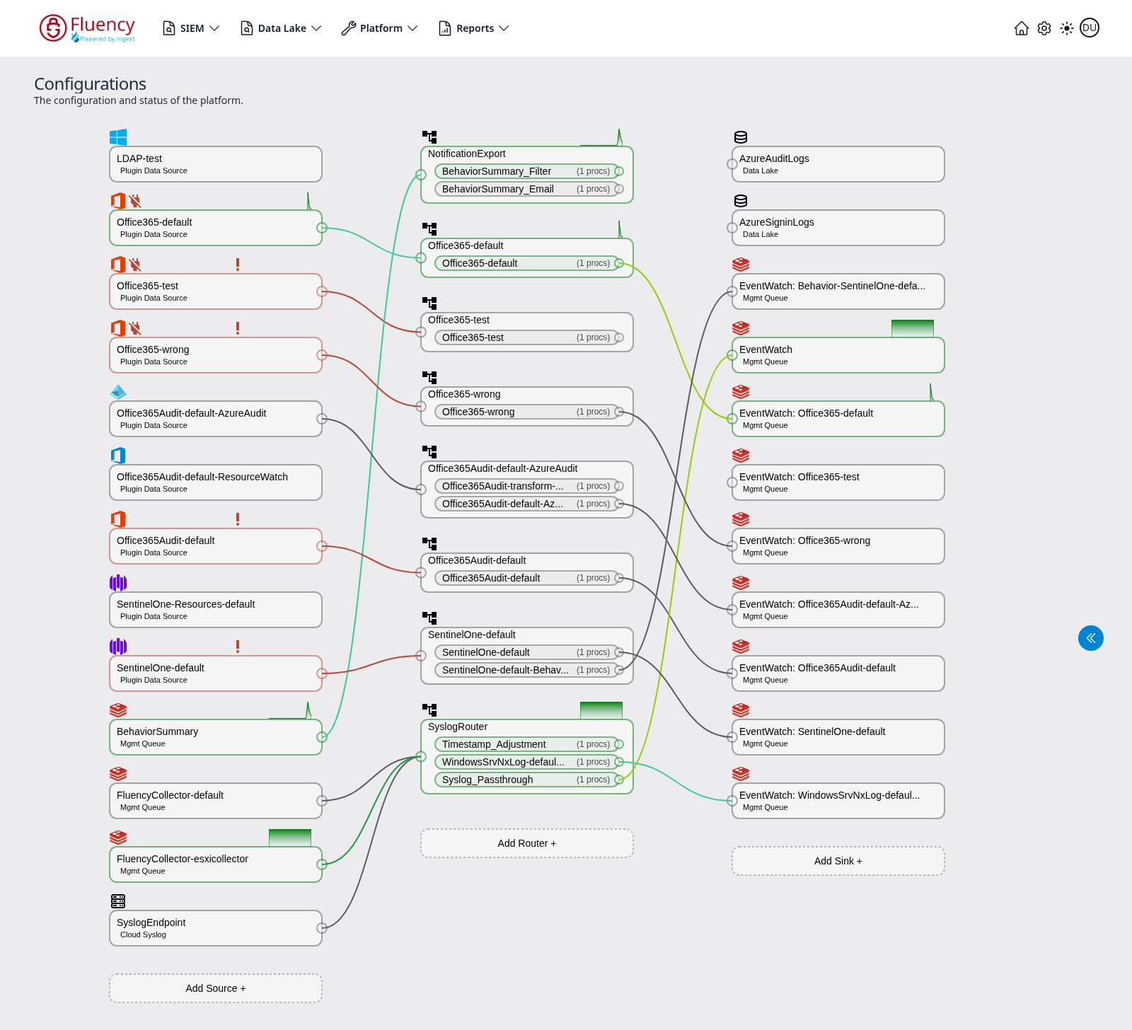
Each router card lists the pipes it runs. A pipe row shows the pipe name and its processor count, for example (1 procs). Routers that are actively moving data are outlined in green and display a small green throughput graph above the card's upper-right corner; idle routers have a gray outline and no graph. A router in error is outlined in red and marked with an exclamation mark above the card.
Small circular ports sit on the edges of each card. Colored lines run from a source's output port to the router's input port, and from each router pipe's output port to a sink, tracing the exact path events take through the platform. Line colors distinguish the individual flows where several cross.
Click Add Router + at the bottom of the Routers column to add a new router.
Creating the Pipe

The properties window is on the far left. When clicking the "Add Router" button, that panel will request a name and description for the new router.
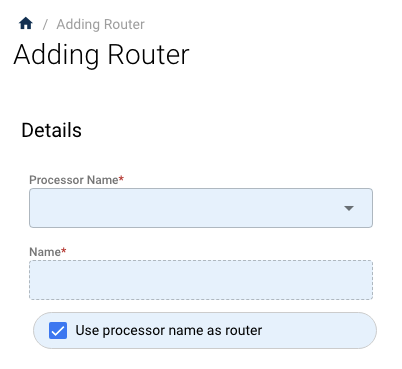
In this example, you are using the process created previously, called LinuxServer.

This will fill in the processor and name the overall router the same name. You can change the overall router name by unchecking "Use processor name as router." Doing that allows you to edit the "Name" field.
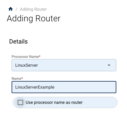
When you save this, the new router will appear to the right in the "Pipe Configuration" panel.
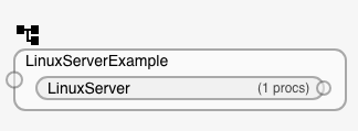
You can see the processor in the pipe by clicking the "LinuxServer" process in the router called "LinuxServerExample."
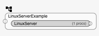
The processor is highlighted and this processor's data can be seen in the properties panel.
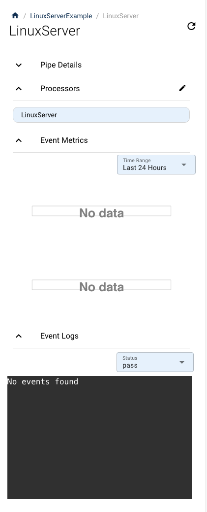
As you can see, the processor is there but there is no data or histograms yet.
Connecting Data
In this example you are going to use a Data Source called "Syslog Endpoint." Syslog is a common data source. In this case you want to move an existing source that is turned on.
Changing the flow is as simple as deleting the current flow and then reassigning the new one. The full procedure is: disable the source, delete the old flow, draw the new flow, then re-enable the source.
Disable the source
If you are moving the flow from a source, you first need to turn the source off.
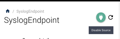
By clicking on the source in the Configuration panel, you will see a green plug to the left of the source name in the properties panel. Click this and accept turning it off.
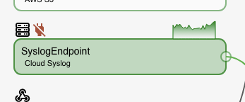
The source will turn red when it is off, and the icon on the panel will have a red plug above it.
Delete the existing flow
At the start of a flow line in the diagram, there is a circle that marks its start.
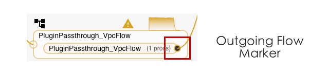
With the source turned off, hover over the outgoing flow line and select it. The flow is highlighted, and a delete (trash) icon appears.
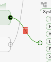
Clicking this will delete the flow. A confirmation box will appear if the flow deletion impacts operations.
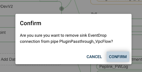
Confirm the deletion and the connection will be removed.
Create the new flow
Now you have a data source with no Router. This allows you to route the data somewhere else.
Start by selecting the source flow. This is done by clicking on the outgoing circle on the flow pipe.
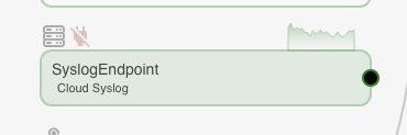
Next, mouse over the destination — the incoming flow marker, the circle to the left of the process you want to connect. A dotted flow line will appear.
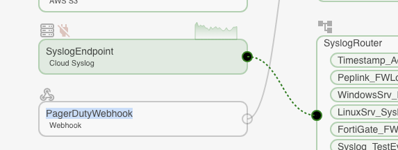
Clicking the incoming marker will present a confirmation for the connection.
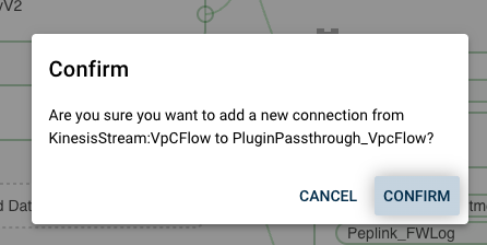
Confirming will establish the connection.
Re-enable the source
There is one more step you need to do to get the data flowing into the process: turn on the data source. Remember you turned it off to create the connection.
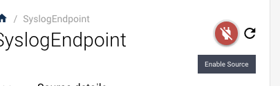
Selecting the source you will see a red plug icon. Click that and accept turning on the source. It will change colors to green when the source is active again.